Backstory and Motivation
Many years ago while browsing YouTube, I discovered a video of a guy making a “CNC Writing Machine” from old DVD drives. I was fascinated to see that, and wanted to make one since then.
After some time I stumbled upon this thing called Brachiograph: World’s Cheapest Simplest Plotter. I would have at least started it but delayed due to lack of commitment; till one of my college seniors asked me to make one. Here we are now, equipped with everything required.
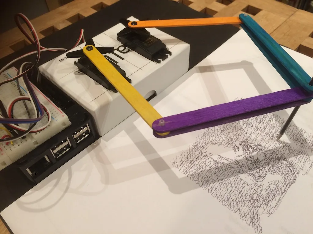
Below is an image of the Brachiograph from the documentation.
Sifting through the documentation, we find this thing called a Pantograph (attached below), labelled as an alternative to the Brachiograph.
I thought the sg90 servos might not be good enough for the Brachiograph, but this Pantograph looks nice and sturdy enough for the purpose. I set out to build one.
Theory
The documentation mentioned certain nice things about the pantograph:
- It has a pair of driver arms and a pair of follower arms.
- The two motors should be positioned as close to each other as possible, and ideally on the same axis (with one mounted upside down on top of other)
- Follower arm should be larger (but not more than twice) in length than the driver; this gives mechanical advantage and allows larger sweep angle for servo.
- If using sg90 servos, the driver and follower arms should not be larger than 5cm and 10cm respectively.
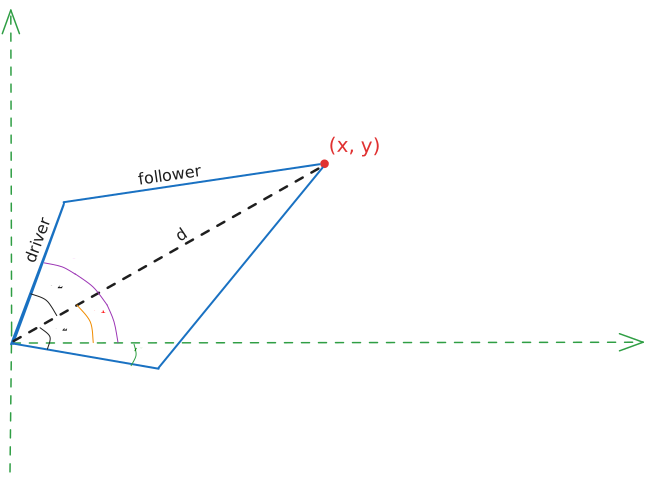
Work out the geometry and joints. I chose to place the servos on the same axis, so it forms a kite-like shape (unlike the pentagon in image above)
Below is the basic design of the plotter.
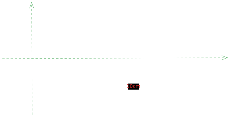
Consider the green dashed lines as coordinate axes, and the servos to be at the origin.
Inverse Kinematics
Now we work out the driving equations, considering one half of the structure.
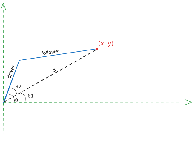 Say we want to move to a point on the plane, then the angles and need to be determined.
is obtained directly from the triangle. For , we use the cosine formula.
The Cosine Formula
For a triangle,
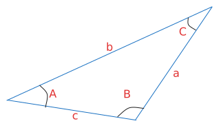
For our model, we get where is the length of driver arm, is the length of follower arm and is the distance of given point from origin.
If represents the angle of servo connected to the upper arm, then
We now include the other half
 We don’t have to compute extra angles.
The servo motor angle (from the x-axis) for the lower half arm is given by
We don’t have to compute extra angles.
The servo motor angle (from the x-axis) for the lower half arm is given by
Build and assembly
- Cut out the arms of given length from a suitable material, I used 5mm sunboard.
- Drill holes and make the rotary joints.
- Stick the servo horn along the driver arm chord.
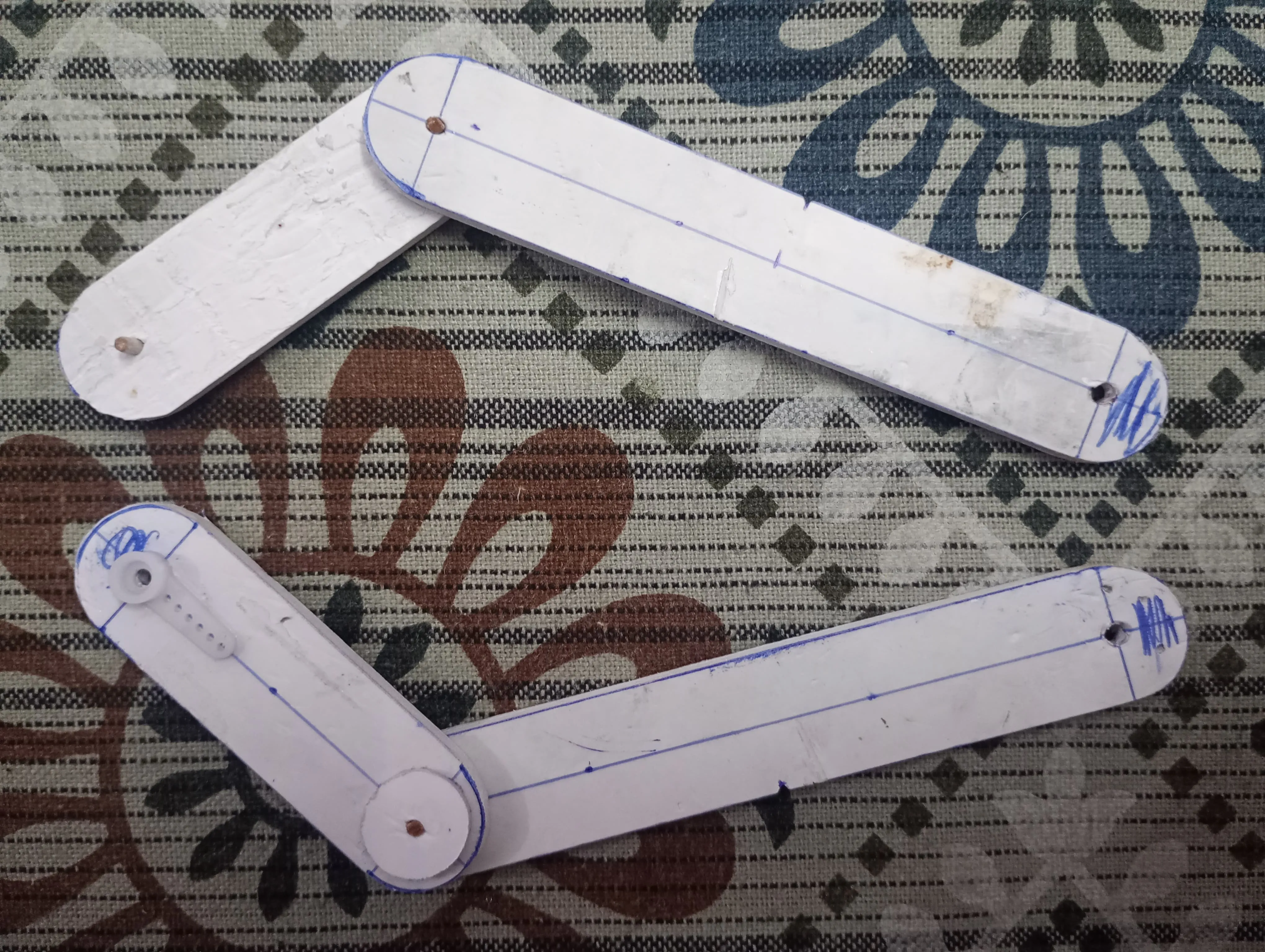 Should look something like this.
- Next, programmatically set both the servos to and attach to horns perpendicular to driver arm chord.
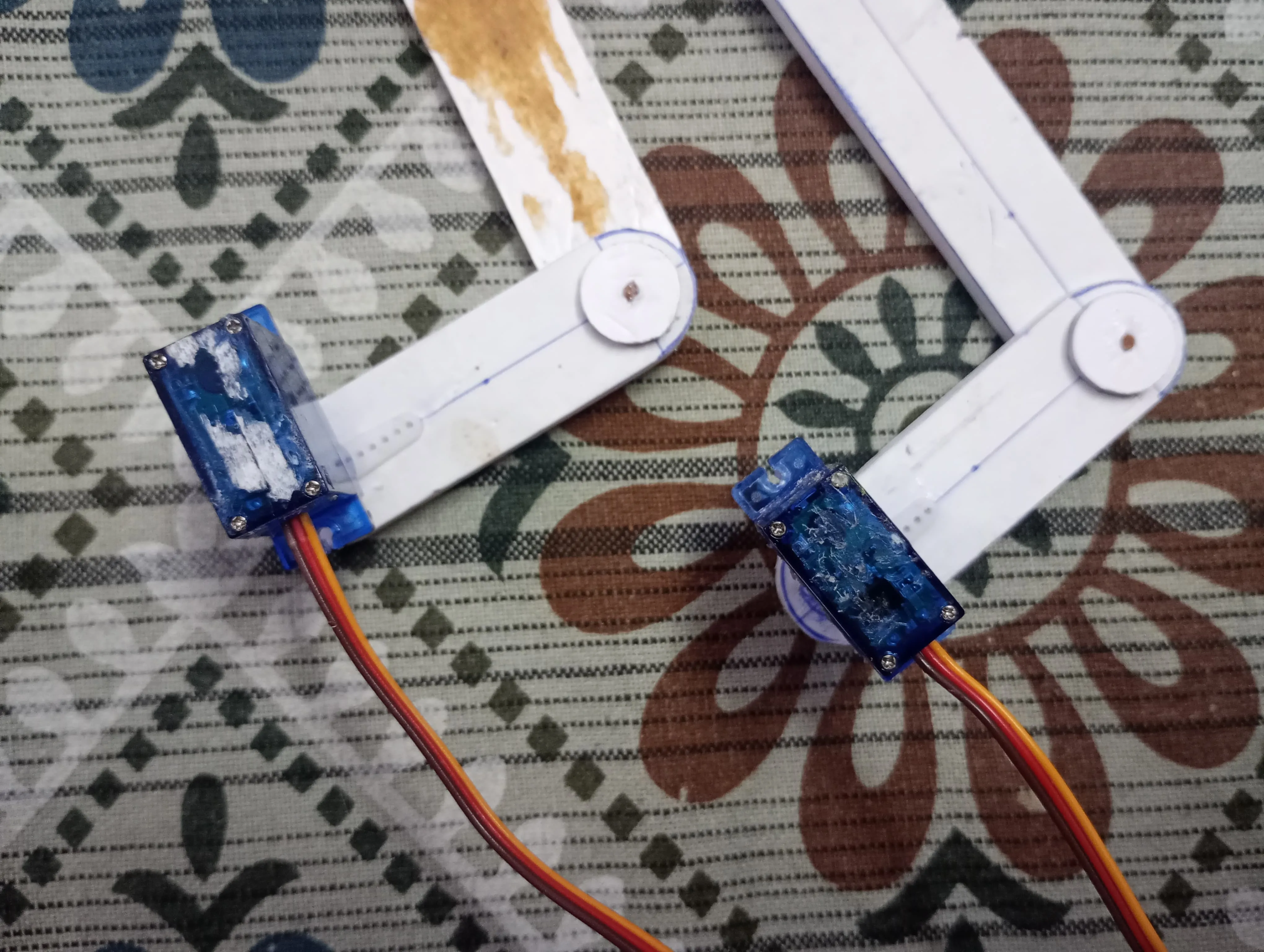
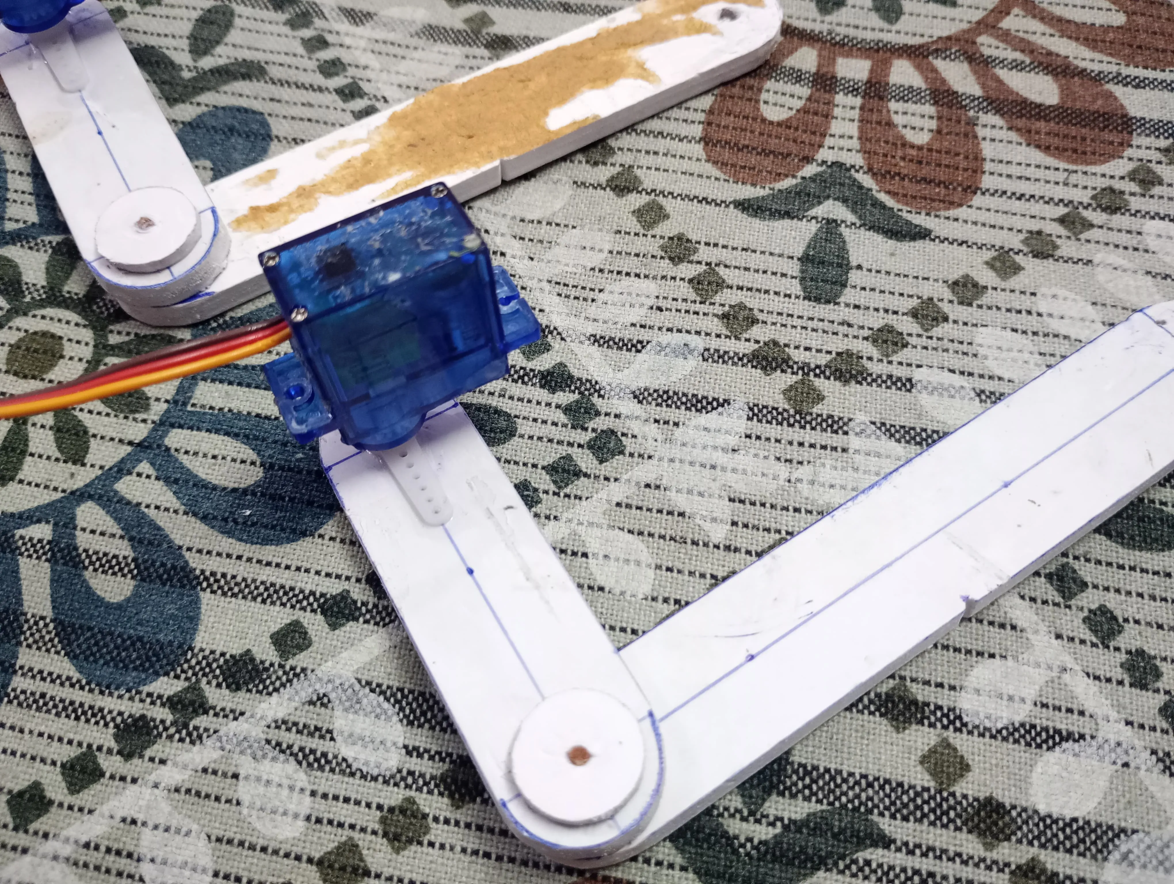
- Attach a pencil/pen at the end effector.
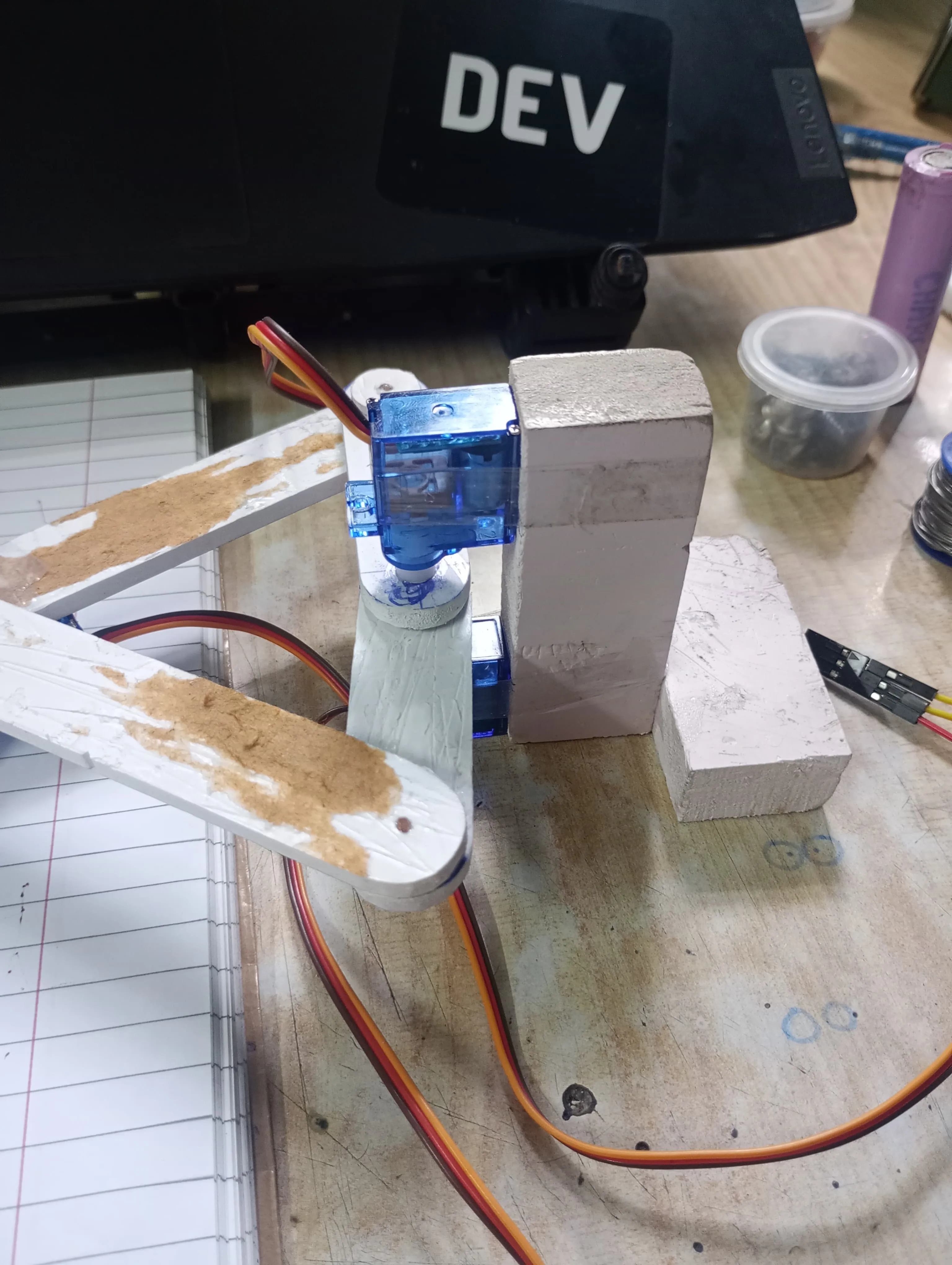
- Make a stand to hold the motors in place.
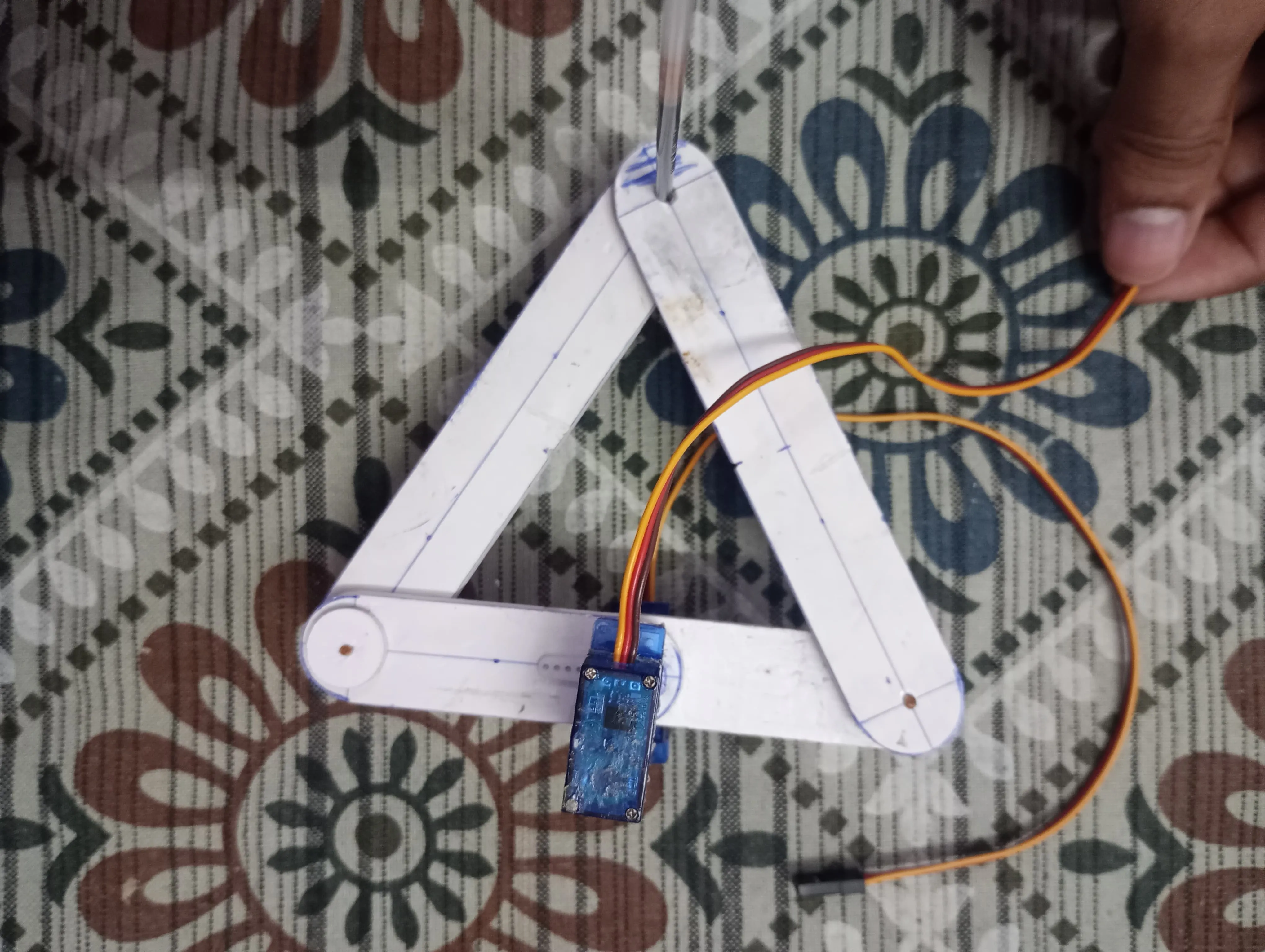
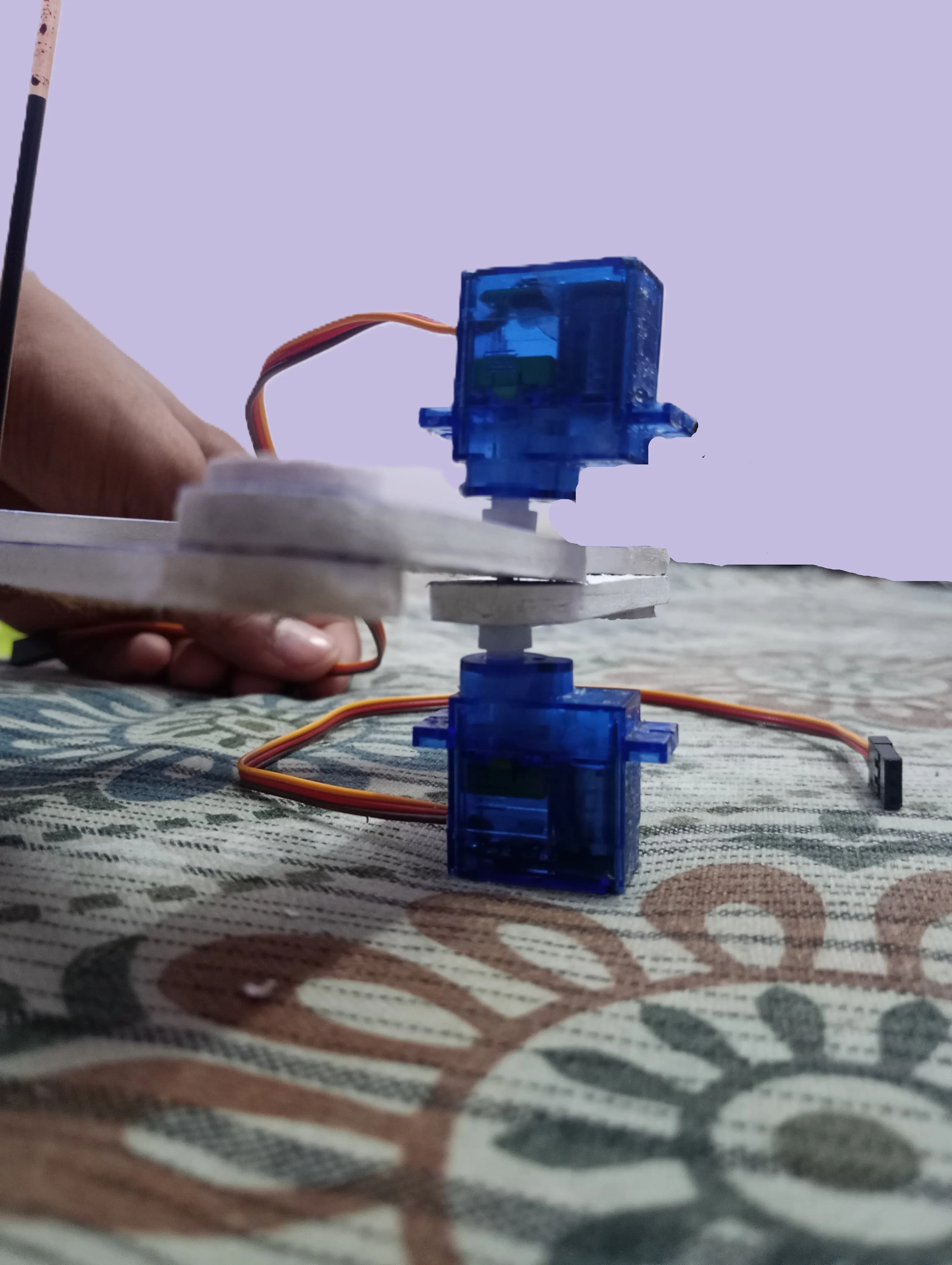
Should look like the below image with the stand.
Connections
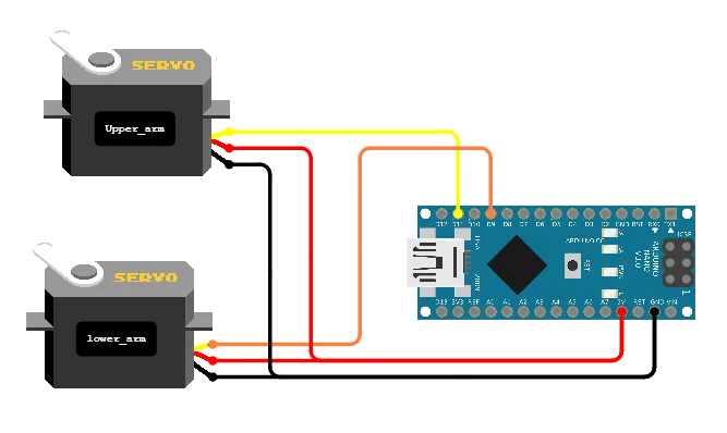 Servo signal wires go to pin 9 and 11.
Servo power supply wires are connected to Arduino’s 5V and GND.
Servo signal wires go to pin 9 and 11.
Servo power supply wires are connected to Arduino’s 5V and GND.
Code
#include <Arduino.h>
#include <math.h>
#include <Servo.h>

#define LOWER_ARM_PIN 9
#define UPPER_ARM_PIN 11

#define MIN_ANGLE 20
#define MAX_ANGLE 125

#define DRIVER_ARM_LENGTH 5
#define FOLLOWER_ARM_LENGTH 10

#define INCREMENT 0.1
#define INCREMENT_INTERVAL 10

Servo lower_arm;
Servo upper_arm;

void move_to(float x, float y)
{
    float d_square = (x * x + y * y);

    float cos_theta = (DRIVER_ARM_LENGTH * FOLLOWER_ARM_LENGTH + d_square - FOLLOWER_ARM_LENGTH * FOLLOWER_ARM_LENGTH) / (2 * DRIVER_ARM_LENGTH * sqrtf(d_square));

    float theta_2 = acosf(cos_theta) * 180 / PI;
    float theta_1 = atan2(y, x) * 180 / PI;

    u8 upper_arm_angle = round(theta_2 + theta_1);
    u8 lower_arm_angle = round(theta_2 - theta_1);

    Serial.print(upper_arm_angle);
    Serial.print(" ");
    Serial.println(lower_arm_angle);

    if (upper_arm_angle > MAX_ANGLE)
        upper_arm_angle = MAX_ANGLE;
    else if (upper_arm_angle < MIN_ANGLE)
        upper_arm_angle = MIN_ANGLE;
    if (lower_arm_angle > MAX_ANGLE)
        lower_arm_angle = MAX_ANGLE;
    else if (lower_arm_angle < MIN_ANGLE)
        lower_arm_angle = MIN_ANGLE;

    upper_arm.write(upper_arm_angle);
    lower_arm.write(lower_arm_angle);
}

void line(float x1, float y1, float x2, float y2)
{
    float delta_x = x2 - x1;
    float delta_y = y2 - y1;

    float distance = sqrt(delta_x * delta_x + delta_y * delta_y);

    double theta = atan2(delta_y, delta_x);

    float inc_x = INCREMENT * cos(theta);
    float inc_y = INCREMENT * sin(theta);

    u16 steps = floor(distance / INCREMENT);

    for (u16 step_count = 0; step_count < steps; ++step_count)
    {
        move_to(x1 + inc_x * step_count, y1 + inc_y * step_count);
        delay(INCREMENT_INTERVAL);
    }
}

void arc(float cx, float cy, float r, u16 theta_1, u16 theta_2)
{
    for (u16 i = theta_1; i < theta_2; i += 2)
    {
        move_to(cx + r * 1.4 * cos(i * PI / 180.0), cy + r * sin(i * PI / 180.0));
        delay(INCREMENT_INTERVAL);
    }
}

void circle(float cx, float cy, float r)
{
    arc(cx, cy, r, 0, 360);
}

void setup()
{
    lower_arm.attach(LOWER_ARM_PIN);
    upper_arm.attach(UPPER_ARM_PIN);
    delay(1000);
}

void loop()
{
    delay(1000);
    line(6, -2, 8, 0);
    delay(1000);
    line(8, 0, 6, 2);
    delay(1000);
    line(6, 2, 6, -2);

    // circle(7,0,1);
}
Code explanation
- Include the required libraries. (I use PlatformIO, so
Arduino.his explicitly needed).
#include <Arduino.h>
#include <math.h>
#include <Servo.h>- Define some constants and variables
The digital pins where respective servos are attached.
#define LOWER_ARM_PIN 9
#define UPPER_ARM_PIN 11
These are the limiting angles, determined by trial and by sweeping servos to extreme positions, incrementally.
#define MIN_ANGLE 20
#define MAX_ANGLE 125
Define the length of arms
#define DRIVER_ARM_LENGTH 5
#define FOLLOWER_ARM_LENGTH 10
Below snippet defines the length of each step while drawing a straight line (0.1cm) and the pause between successive steps (10ms)
#define INCREMENT 0.1
#define INCREMENT_INTERVAL 10
Declare the Servo library objects, used to control the motors.
Servo lower_arm;
Servo upper_arm;- Define the setup function and attach the servos.
void setup()
{
    lower_arm.attach(LOWER_ARM_PIN);
    upper_arm.attach(UPPER_ARM_PIN);
    delay(1000);
}- Define a function to implement the inverse kinematics which moves the end effector (pen tip) to the desired point in our coordinate system. Compute the distances and apply the cosine formula to get the angles , , and . Then perform the checks so that angle stays within the limit and move the servo to calculated point.
void move_to(float x, float y)
{
    float d_square = (x * x + y * y);

    float cos_theta = (DRIVER_ARM_LENGTH * FOLLOWER_ARM_LENGTH + d_square - FOLLOWER_ARM_LENGTH * FOLLOWER_ARM_LENGTH) / (2 * DRIVER_ARM_LENGTH * sqrtf(d_square));

    float theta_2 = acosf(cos_theta) * 180 / PI;
    float theta_1 = atan2(y, x) * 180 / PI;

    u8 upper_arm_angle = round(theta_2 + theta_1);
    u8 lower_arm_angle = round(theta_2 - theta_1);

    if (upper_arm_angle > MAX_ANGLE)
        upper_arm_angle = MAX_ANGLE;
    else if (upper_arm_angle < MIN_ANGLE)
        upper_arm_angle = MIN_ANGLE;
    if (lower_arm_angle > MAX_ANGLE)
        lower_arm_angle = MAX_ANGLE;
    else if (lower_arm_angle < MIN_ANGLE)
        lower_arm_angle = MIN_ANGLE;

    upper_arm.write(upper_arm_angle);
    lower_arm.write(lower_arm_angle);
}- Next define a function to draw a straight line from point to point .
void line(float x1, float y1, float x2, float y2)
{
    float delta_x = x2 - x1;
    float delta_y = y2 - y1;

    float distance = sqrt(delta_x * delta_x + delta_y * delta_y);

    double theta = atan2(delta_y, delta_x);

    float inc_x = INCREMENT * cos(theta);
    float inc_y = INCREMENT * sin(theta);

    u16 steps = floor(distance / INCREMENT);

    for (u16 step_count = 0; step_count < steps; ++step_count)
    {
        move_to(x1 + inc_x * step_count, y1 + inc_y * step_count);
        delay(INCREMENT_INTERVAL);
    }
}
Now you may have a question why not just move_to directly?
move_to(x1, y1);
delay(some_travel_delay);
move_to(x2, y2);
I had the same question, so I followed the above code and it resulted in a curved line line shown below. Yay! This may be because of how the arms moves, in circular sense.
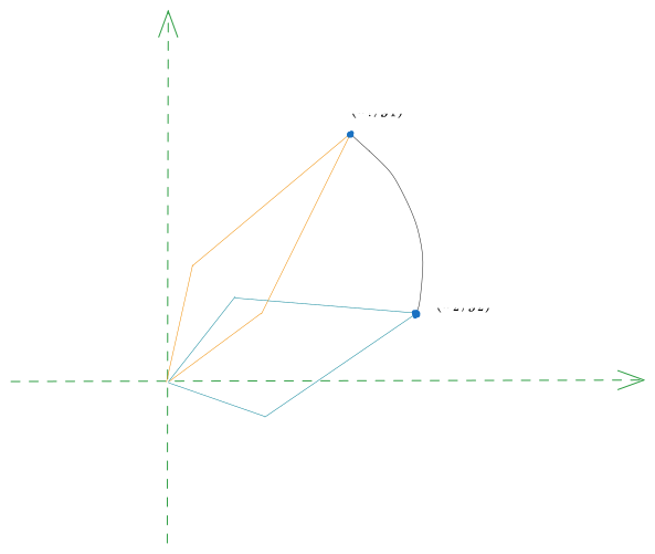
To fix this issue, we need to add several small steps in between the initial point and final point.
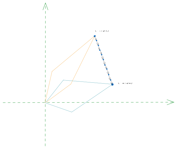
The function uses some vector algebra and trigonometry to take a step of length INCREMENT_LENGTH in the direction of line, and gradually moves to final point.
- Next define a function to draw an arc given the center, radius, initial and final angles.
The function executes a series of
move_to()calls for each degree fromtheta_1totheta_2.
void arc(float cx, float cy, float r, u16 theta_1, u16 theta_2)
{
    for (u16 i = theta_1; i < theta_2; i+=2)
    {
        move_to(cx + r * 1.4 * cos(i * PI / 180.0), cy + r * sin(i * PI / 180.0));
        delay(INCREMENT_INTERVAL);
    }
}
Demonstration
Here is a clip showing the plotter in action!
Future plans
- Currently, the machine can only draw basic lines and curves, so make it able to draw vector images.
- Attach a third servo at the end effector to pick up / put down the pen when not required.